# PrusaConnect ESP32-CAM
This repository includes source code and firmware releases for the ESP32-cam module programmed in the Arduino IDE
This project uses other libraries. It is necessary to install them in the arduino IDE.
- App [Arduino IDE 2.3.2](https://www.arduino.cc/en/software)
- MCU support [ESP32 2.0.15](https://github.com/espressif/arduino-esp32)
- Library [ESPAsyncWebSrv 1.2.7](https://github.com/dvarrel/ESPAsyncWebSrv)
- Library [AsyncTCP 1.1.4](https://github.com/dvarrel/AsyncTCP)
- Library [ArduinoJson 7.0.4](https://github.com/bblanchon/ArduinoJson)
- Library [UniqueID 1.3.0](https://github.com/ricaun/ArduinoUniqueID)
What we need for functionality
- ESP32-CAM AI-thinker board with OV2640 camera module [ here ](#esp32)
- Module board version [here](#different_mcu)
- Install the necessary libraries in the Arduino IDE [ here ](#arduino_lib)
- Arduino IDE configuration [ here ](#arduino_cfg)
- How to flash firmware to ESP32-cam and connect to PrusaConnect [ here ](https://help.prusa3d.com/preview/guide/esp32-cam-for-prusa-connect_673528)
- How to flash binnary files to ESP32-cam board from Linux/MAC/Windows [ here ](#flash_fw)
- How to reset configuration to factory settings [here](#factory_cfg)
- Status LED [ here ](#status_led)
- Schematic main board is [here](#schematic)
- Issue with FLASH LED on the main board [here](#led_issue)
- External WiFi antena [here](#ext_wifi)
- Power supply [here](#power_supply)
- Debug logs [here](#logs)
- Serial console configuration [here](#serial_cfg)
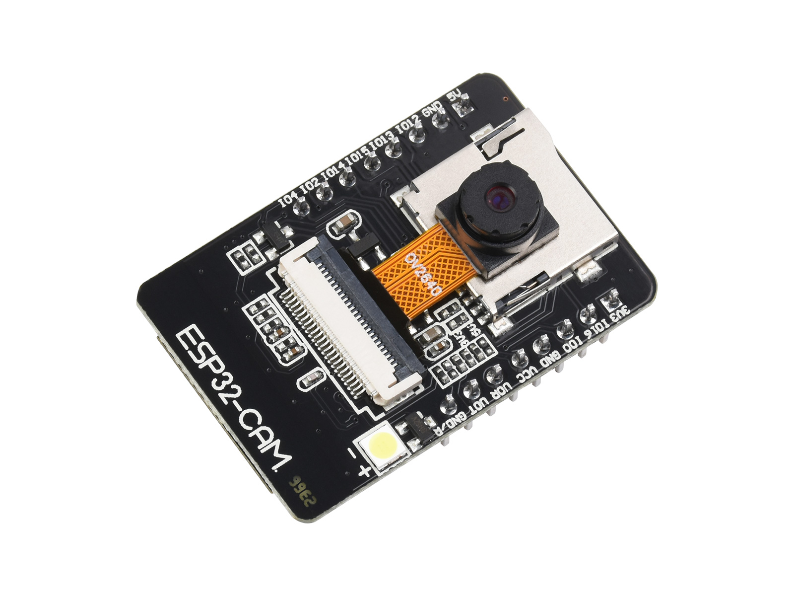
## ESP32-CAM AI-thinker board
It's a few dolars board with **ESP32** MCU and Camera. It's neccesary to buy a board with **camera module OV2640**. The board is sold without a programmer by default. It is possible to program it using the FTDI USB to UART converter, or purchase an official programmer for the board. We recommend purchasing a official programmer. It can save a lot of trouble with connecting and programming the board. There are currently [2 different board version](#different_mcu) but only one is compatible with the official programmer.
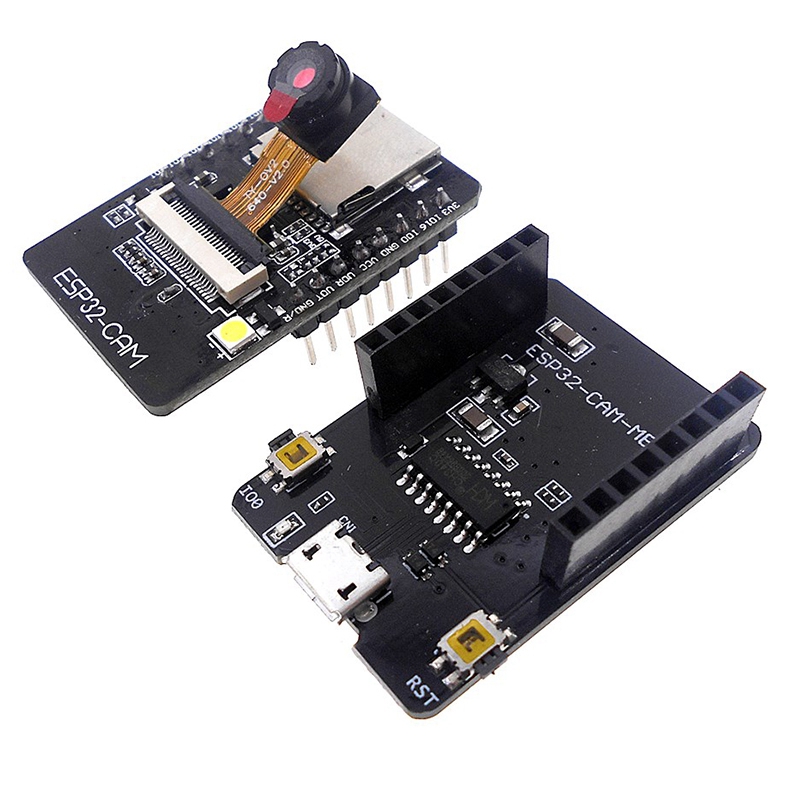
 In the next picture we can see **ESP32-CAM** board and programator for board.
 It's neccesary use a camera version **OV2640**. If using a different camera, then it may be necessary to modify the camera's pinout, or some camera settings may not work correctly. We recommend using a camera module with a viewing angle of 120° or 160°.
These are currently known or tested camera modules:
| Camera chip | FOV | Resolution | Tested | Works | Description |
|-------------|------|------------|--------|-------|------------------------------------------|
| OV2640 | 30° | 2MP | No | N/A | |
| OV2640 | 44° | 2MP | No | N/A | |
| OV2640 | 66° | 2MP | Yes | Yes | Recomended. Standard camera module |
| OV2640 | 120° | 2MP | Yes | Yes | Recomended |
| OV2640 | 160° | 2MP | Yes | Yes | Recomended |
| OV2640 | 200° | 2MP | No | N/A | |
| OV2640 | 222° | 2MP | No | N/A | |
| OV2640IR | 160° | 2MP | Yes | Yes | |
| OV8225N | 66° | 2MP | Yes | Yes | |
| OV3360 | 66° | 3MP | Yes | Yes | |
| OV5640-AF | 72° | 5MP | Yes | Yes | Overheating, slow photo loading |
## Different MCU version
There are currently 2 versions of the board, but only one version is possible programming via CH340. The blue rectangle shows the differences between the HW versions.
It's neccesary use a camera version **OV2640**. If using a different camera, then it may be necessary to modify the camera's pinout, or some camera settings may not work correctly. We recommend using a camera module with a viewing angle of 120° or 160°.
These are currently known or tested camera modules:
| Camera chip | FOV | Resolution | Tested | Works | Description |
|-------------|------|------------|--------|-------|------------------------------------------|
| OV2640 | 30° | 2MP | No | N/A | |
| OV2640 | 44° | 2MP | No | N/A | |
| OV2640 | 66° | 2MP | Yes | Yes | Recomended. Standard camera module |
| OV2640 | 120° | 2MP | Yes | Yes | Recomended |
| OV2640 | 160° | 2MP | Yes | Yes | Recomended |
| OV2640 | 200° | 2MP | No | N/A | |
| OV2640 | 222° | 2MP | No | N/A | |
| OV2640IR | 160° | 2MP | Yes | Yes | |
| OV8225N | 66° | 2MP | Yes | Yes | |
| OV3360 | 66° | 3MP | Yes | Yes | |
| OV5640-AF | 72° | 5MP | Yes | Yes | Overheating, slow photo loading |
## Different MCU version
There are currently 2 versions of the board, but only one version is possible programming via CH340. The blue rectangle shows the differences between the HW versions.
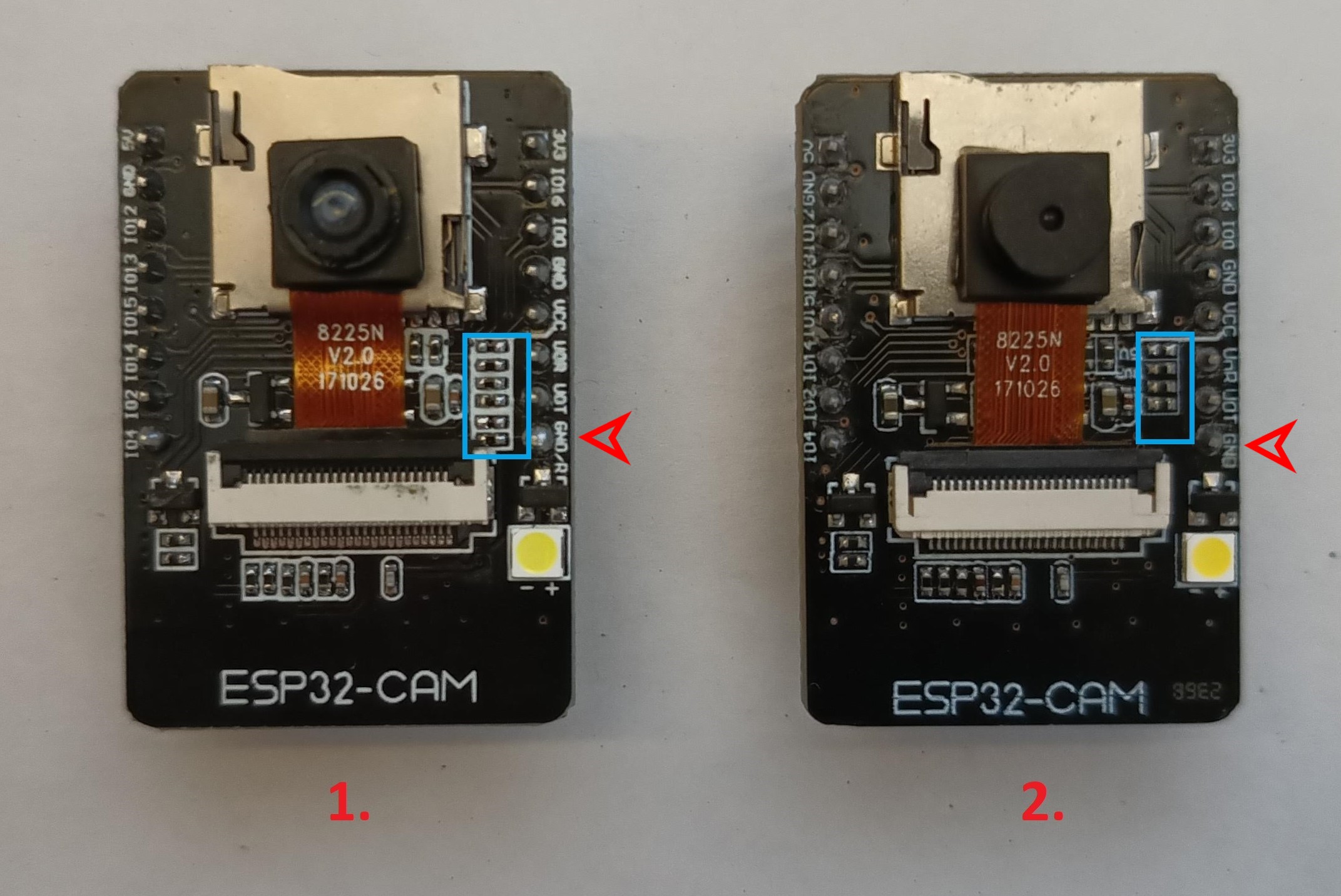 The red arrow points to a pin that differs between these boards. In version 1, this pin is used for MCU RESET (GND/R). In version 2, this pin serves as ground (GND). Version 1 can be programmed via CH340, whereas version 2 cannot be programmed via CH340. For version 2, we tested programming via FT232RL or CP2102, and the programming process worked successfully.
## Necessary libraries in the Arduino IDE
Software compilation was done in Arduino IDE 2.3.2. To ensure proper functionality, it is necessary to install support for ESP32 boards into Arduino IDE, as well as several other libraries
At the first step we need to install support for **ESP32 board**.
**File** -> **Preferences** -> **Additional boards managers URLs**
```
https://raw.githubusercontent.com/espressif/arduino-esp32/gh-pages/package_esp32_index.json
```
then go to **Tools** -> **Board** -> **Boards Manager...** and install module **ESP32** by **Espressif Systems**, version **2.0.15**
Next step is to install the necessary libraries. Go to **Sketch** -> **Include Library** -> **Manage Libraries...** or you can use **Ctrl+Shift+I**. Then you can search for the necessary libraries and install them.
- Library [ESPAsyncWebSrv by dvarrel 1.2.7](https://github.com/dvarrel/ESPAsyncWebSrv)
- Library [AsyncTCP by dvarrel 1.1.4](https://github.com/dvarrel/AsyncTCP)
- Library [ArduinoJson by bblanchon 7.0.4](https://github.com/bblanchon/ArduinoJson)
- Library [UniqueID by Luiz Henrique Cassettari1.3.0](https://github.com/ricaun/ArduinoUniqueID)
## Arduino IDE configuration
Board configuration in the arduino IDE 2.3.2
- Tools -> Board -> ESP32 Arduino -> AI Thinker ESP32
- Tools -> Flash frequency -> 80MHz
- Tools -> Core Debug Level -> None
- Tools -> Erase all Flash Before Sketch Upload -> Disable **(first flash, new board = enable. otherwise = disable)**
- Tools -> Flash Mode -> DIO
- Tools -> Partition scheme -> Minimal SPIFFS (1.9MB APP with OTA/190KB SPIFFS)
When flashing the firmware to a new, empty ESP32-CAM device for the first time, it is necessary to use the 'Erase' function.
This can be found under **Tools** -> **Erase all Flash Before Sketch Upload** -> **Enable**.
After the initial firmware upload to the MCU, it's necessary to disable this option. If you do not disable this option, your camera configuration will continue to be erased from the flash memory after uploading new firmware from the Arduino IDE.
## How to flash binnary files to ESP32-cam board from Linux/MAC/Windows
To upload the firmware on the MAC or Linux platform, you must use the console. First, ensure you have installed esptool for Python. You can find it on the manufacturer's website, ESPRESSIF, [here](https://docs.espressif.com/projects/esp-at/en/latest/esp32/Get_Started/Downloading_guide.html).
And command for FLASH FW is here, where **/dev/ttya0** is your serial interface for communication with the ESP32-cam board.
```
python3 -m esptool -p /dev/ttya0 -b 460800 --before default_reset --after hard_reset --chip
esp32 write_flash --erase-all --flash_mode dio --flash_size 4MB --flash_freq 80m 0x1000
ESP32_PrusaConnectCam_web.ino.bootloader.bin 0x8000
ESP32_PrusaConnectCam_web.ino.partitions.bin 0x10000 ESP32_PrusaConnectCam_web.ino.bin
```
Here is the partitions table:
| Name | Type | SubType | Offset | Size | Flags |
|---------|---------|---------|----------|----------|-------|
| nvs | data | nvs | 0x9000 | 0x5000 | |
| otadata | data | ota | 0xe000 | 0x2000 | |
| app0 | app | ota_0 | 0x10000 | 0x1E0000 | |
| app1 | app | ota_1 | 0x1F0000 | 0x1E0000 | |
| spiffs | data | spiffs | 0x3D0000 | 0x20000 | |
| coredump| data | coredump| 0x3F0000 | 0x10000 | |
However, for uploading the firmware, it's important to use this configuration of addresses and files:
- address **0x1000** - **ESP32_PrusaConnectCam.ino.bootloader.bin**
- address **0x8000** - **ESP32_PrusaConnectCam.ino.partitions.bin**
- address **0x10000** - **ESP32_PrusaConnectCam.ino.bin**
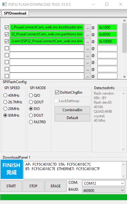
Here is tool and configuration for [windows platform](https://www.espressif.com/en/support/download/other-tools)
The red arrow points to a pin that differs between these boards. In version 1, this pin is used for MCU RESET (GND/R). In version 2, this pin serves as ground (GND). Version 1 can be programmed via CH340, whereas version 2 cannot be programmed via CH340. For version 2, we tested programming via FT232RL or CP2102, and the programming process worked successfully.
## Necessary libraries in the Arduino IDE
Software compilation was done in Arduino IDE 2.3.2. To ensure proper functionality, it is necessary to install support for ESP32 boards into Arduino IDE, as well as several other libraries
At the first step we need to install support for **ESP32 board**.
**File** -> **Preferences** -> **Additional boards managers URLs**
```
https://raw.githubusercontent.com/espressif/arduino-esp32/gh-pages/package_esp32_index.json
```
then go to **Tools** -> **Board** -> **Boards Manager...** and install module **ESP32** by **Espressif Systems**, version **2.0.15**
Next step is to install the necessary libraries. Go to **Sketch** -> **Include Library** -> **Manage Libraries...** or you can use **Ctrl+Shift+I**. Then you can search for the necessary libraries and install them.
- Library [ESPAsyncWebSrv by dvarrel 1.2.7](https://github.com/dvarrel/ESPAsyncWebSrv)
- Library [AsyncTCP by dvarrel 1.1.4](https://github.com/dvarrel/AsyncTCP)
- Library [ArduinoJson by bblanchon 7.0.4](https://github.com/bblanchon/ArduinoJson)
- Library [UniqueID by Luiz Henrique Cassettari1.3.0](https://github.com/ricaun/ArduinoUniqueID)
## Arduino IDE configuration
Board configuration in the arduino IDE 2.3.2
- Tools -> Board -> ESP32 Arduino -> AI Thinker ESP32
- Tools -> Flash frequency -> 80MHz
- Tools -> Core Debug Level -> None
- Tools -> Erase all Flash Before Sketch Upload -> Disable **(first flash, new board = enable. otherwise = disable)**
- Tools -> Flash Mode -> DIO
- Tools -> Partition scheme -> Minimal SPIFFS (1.9MB APP with OTA/190KB SPIFFS)
When flashing the firmware to a new, empty ESP32-CAM device for the first time, it is necessary to use the 'Erase' function.
This can be found under **Tools** -> **Erase all Flash Before Sketch Upload** -> **Enable**.
After the initial firmware upload to the MCU, it's necessary to disable this option. If you do not disable this option, your camera configuration will continue to be erased from the flash memory after uploading new firmware from the Arduino IDE.
## How to flash binnary files to ESP32-cam board from Linux/MAC/Windows
To upload the firmware on the MAC or Linux platform, you must use the console. First, ensure you have installed esptool for Python. You can find it on the manufacturer's website, ESPRESSIF, [here](https://docs.espressif.com/projects/esp-at/en/latest/esp32/Get_Started/Downloading_guide.html).
And command for FLASH FW is here, where **/dev/ttya0** is your serial interface for communication with the ESP32-cam board.
```
python3 -m esptool -p /dev/ttya0 -b 460800 --before default_reset --after hard_reset --chip
esp32 write_flash --erase-all --flash_mode dio --flash_size 4MB --flash_freq 80m 0x1000
ESP32_PrusaConnectCam_web.ino.bootloader.bin 0x8000
ESP32_PrusaConnectCam_web.ino.partitions.bin 0x10000 ESP32_PrusaConnectCam_web.ino.bin
```
Here is the partitions table:
| Name | Type | SubType | Offset | Size | Flags |
|---------|---------|---------|----------|----------|-------|
| nvs | data | nvs | 0x9000 | 0x5000 | |
| otadata | data | ota | 0xe000 | 0x2000 | |
| app0 | app | ota_0 | 0x10000 | 0x1E0000 | |
| app1 | app | ota_1 | 0x1F0000 | 0x1E0000 | |
| spiffs | data | spiffs | 0x3D0000 | 0x20000 | |
| coredump| data | coredump| 0x3F0000 | 0x10000 | |
However, for uploading the firmware, it's important to use this configuration of addresses and files:
- address **0x1000** - **ESP32_PrusaConnectCam.ino.bootloader.bin**
- address **0x8000** - **ESP32_PrusaConnectCam.ino.partitions.bin**
- address **0x10000** - **ESP32_PrusaConnectCam.ino.bin**
Here is tool and configuration for [windows platform](https://www.espressif.com/en/support/download/other-tools)
 It's necessary to erase the FLASH using the **ERASE** button before the first firmware flash.
 ## How to reset configuration to factory settings
To reset the settings to factory defaults, follow these instructions:
## How to reset configuration to factory settings
To reset the settings to factory defaults, follow these instructions:
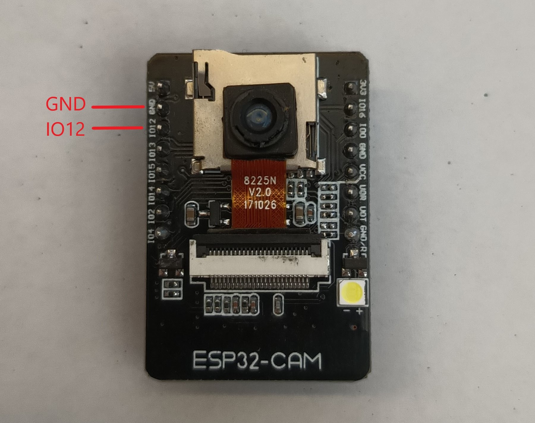 - Connect PIN **IO12** to **ground**.
- **Plug in** the power supply.
- Wait for **10 seconds**.
- After 10 seconds, the **FLASH LED will start flashing**.
- **Disconnect** PIN **IO12** from **ground** (but do't disconnect the power supply).
- After disconnecting **IO12** from **ground**, the **FLASH LED** will **stop flashing**, and the MCU will **automatically rebooted**.
- Now the MCU is in the factory settings.
## Status LED
On the board, there is a status LED that provides a visual indicator of the module's current status
through blinking at defined intervals.
- Connect PIN **IO12** to **ground**.
- **Plug in** the power supply.
- Wait for **10 seconds**.
- After 10 seconds, the **FLASH LED will start flashing**.
- **Disconnect** PIN **IO12** from **ground** (but do't disconnect the power supply).
- After disconnecting **IO12** from **ground**, the **FLASH LED** will **stop flashing**, and the MCU will **automatically rebooted**.
- Now the MCU is in the factory settings.
## Status LED
On the board, there is a status LED that provides a visual indicator of the module's current status
through blinking at defined intervals.
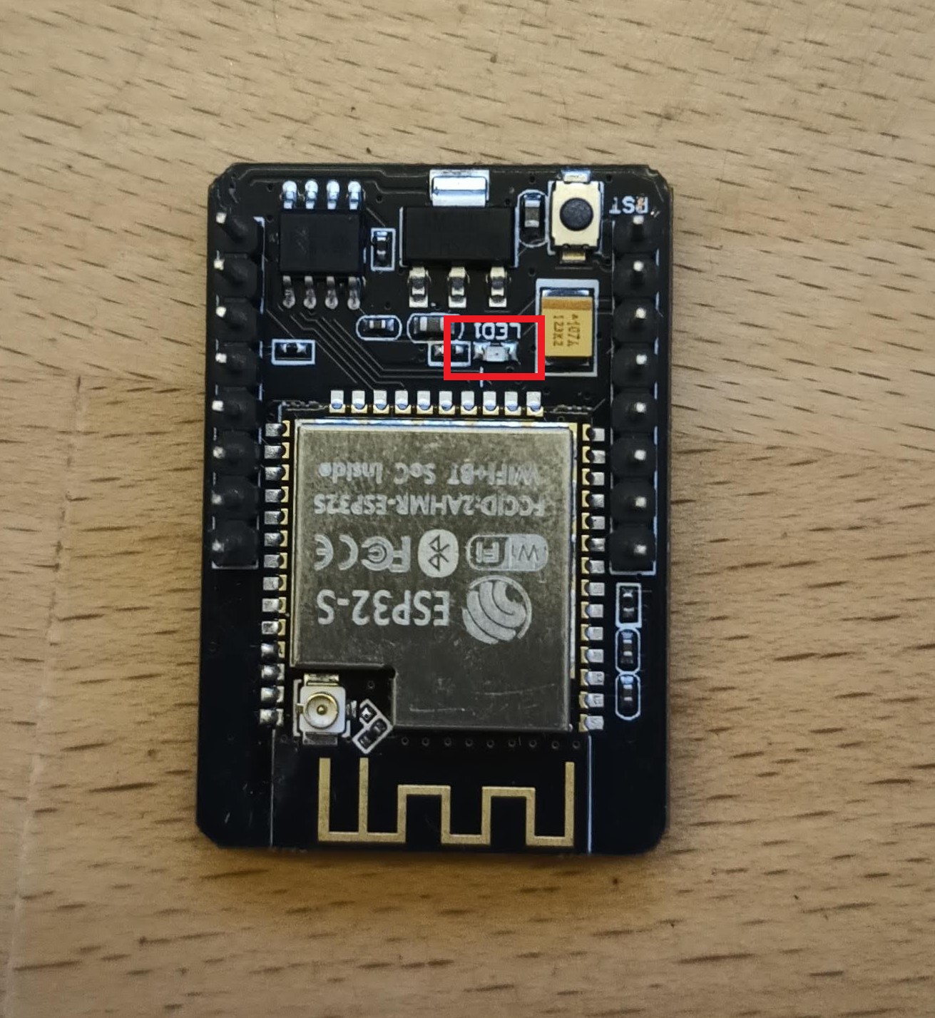 Upon module activation, the LED illuminates. After processor initialization, the LED exhibits different blinking intervals based on the current mode of the module
- **Just service AP Mode:** The LED blinks every **400 ms**, indicating the module's availability in service AP mode.
- **Connecting to WiFi AP:** While connecting to a WiFi Access Point, the LED blinks at intervals of **800 ms**.
- **Connected to WiFi Network:** Upon successful connection to a WiFi network, the LED blinks at intervals of **4000 ms**, signaling a stable connection.
- **Problematic State:** If an issue or error occurs, the LED accelerates its blinking to every **100 ms**.
## Schematic for ESP32-cam board
Upon module activation, the LED illuminates. After processor initialization, the LED exhibits different blinking intervals based on the current mode of the module
- **Just service AP Mode:** The LED blinks every **400 ms**, indicating the module's availability in service AP mode.
- **Connecting to WiFi AP:** While connecting to a WiFi Access Point, the LED blinks at intervals of **800 ms**.
- **Connected to WiFi Network:** Upon successful connection to a WiFi network, the LED blinks at intervals of **4000 ms**, signaling a stable connection.
- **Problematic State:** If an issue or error occurs, the LED accelerates its blinking to every **100 ms**.
## Schematic for ESP32-cam board
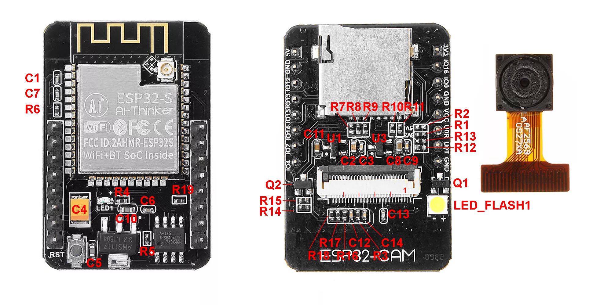
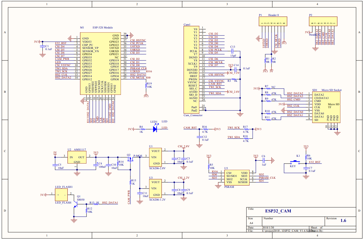 Parts description
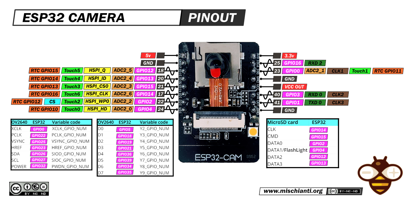
 Pinout
 ## FLASH LED issue
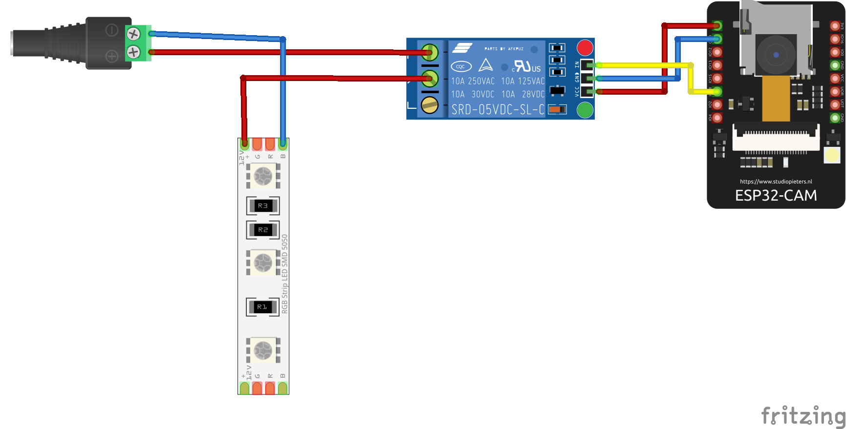
The board has a problem with the FLASH LED, as it lacks any current limitation for the LED. Consequently, frequent use of the FLASH LED can lead to corruption, due to excessive current flow.
One simple solution is to connect an external LED via a relay, transistor, or MOSFET to the board, as shown in the next picture. Using a relay is not ideal, but it provides a simple solution.
## FLASH LED issue
The board has a problem with the FLASH LED, as it lacks any current limitation for the LED. Consequently, frequent use of the FLASH LED can lead to corruption, due to excessive current flow.
One simple solution is to connect an external LED via a relay, transistor, or MOSFET to the board, as shown in the next picture. Using a relay is not ideal, but it provides a simple solution.
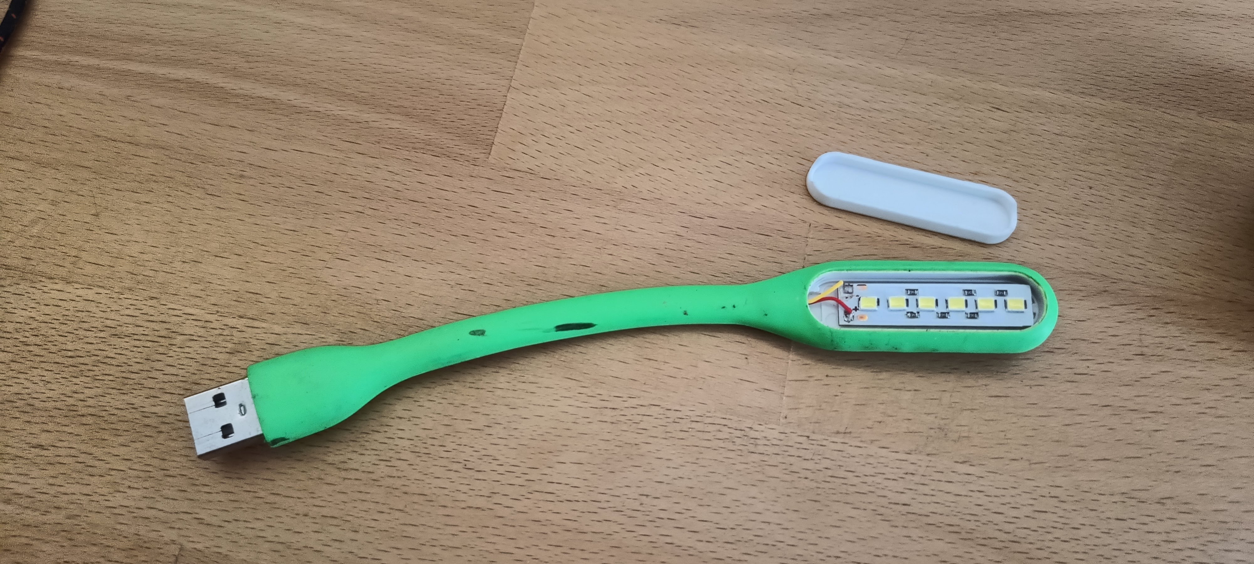
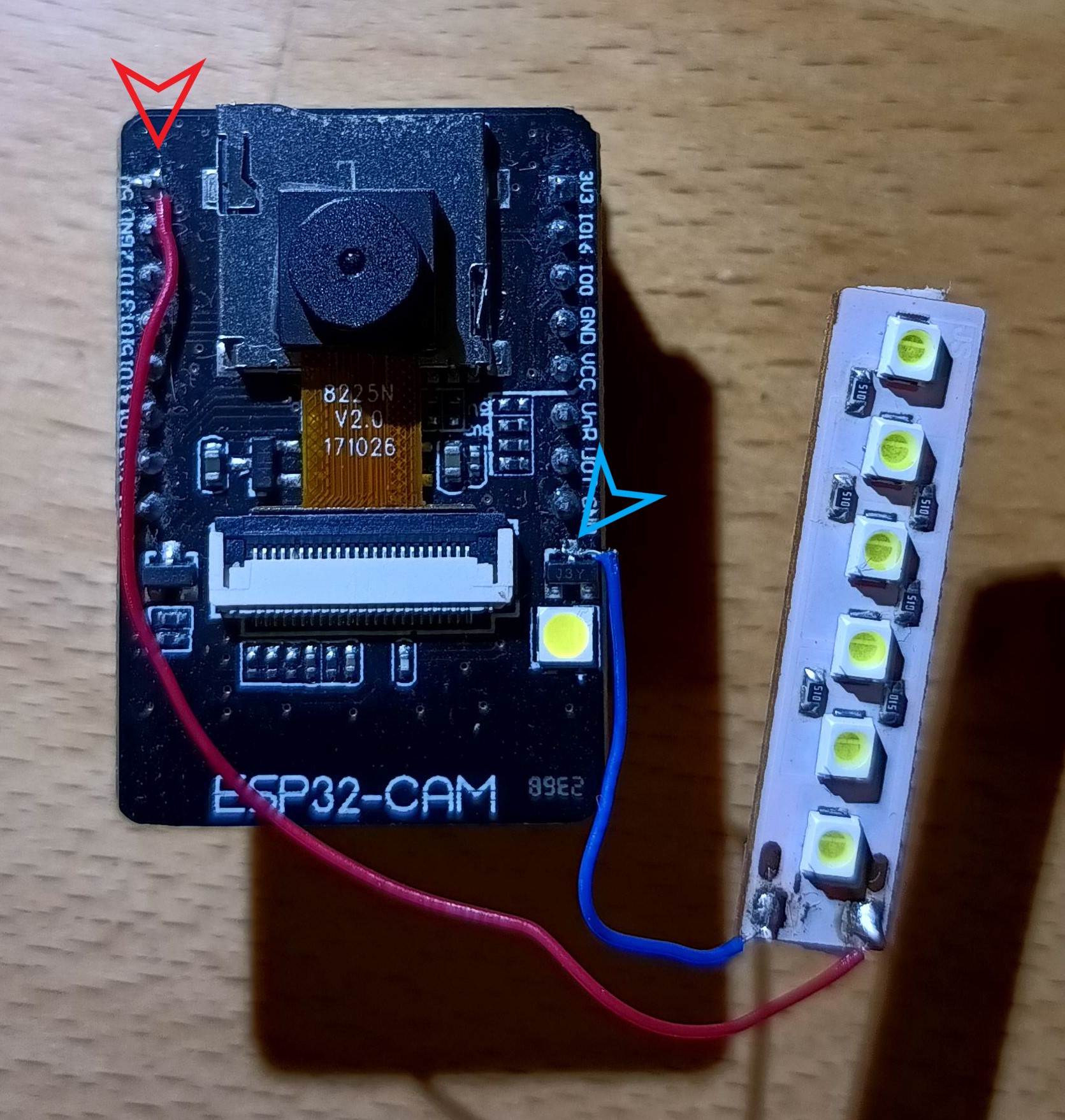
 Another solution is to use a LED COB or a USB LED lamp. I utilized a board from a simple USB LED lamp. The transistor has a current limitation of 500mA, and my USB lamp has a current consumption of 180mA. The original LED has a current consumption of 60-80mA, and the USB lamp has a current consumption of approximately 180mA. After calculation, the total current consumption is approximately 260mA, which falls within the current limitation of the transistor. Therefore, it is possible to solder the negative wire from the COB LED or the USB LED lamp to the transistor. The positive wire needs to be soldered to +5V.
This is my USB LED lamp
Another solution is to use a LED COB or a USB LED lamp. I utilized a board from a simple USB LED lamp. The transistor has a current limitation of 500mA, and my USB lamp has a current consumption of 180mA. The original LED has a current consumption of 60-80mA, and the USB lamp has a current consumption of approximately 180mA. After calculation, the total current consumption is approximately 260mA, which falls within the current limitation of the transistor. Therefore, it is possible to solder the negative wire from the COB LED or the USB LED lamp to the transistor. The positive wire needs to be soldered to +5V.
This is my USB LED lamp
 The next step is to solder the negative wire from the LED lamp to the transistor collector, and the positive wire from the LED lamp to the +5V on the board.
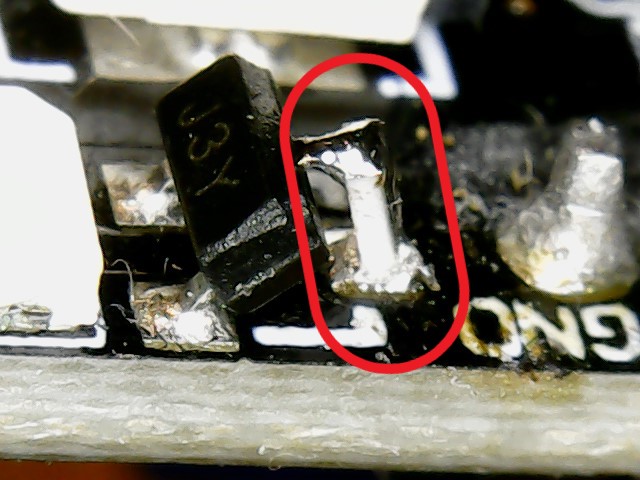
 The third option is to solder a resistor between the collector of the transistor and the PCB. I used a 10-ohm resistor in a 0603 package. This option is more complicated for users with limited soldering experience.
 ## External/internal WiFi antenna
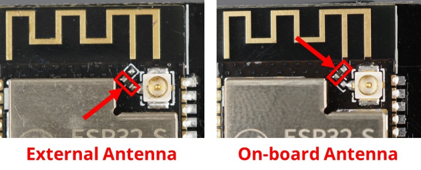
The standard ESP32-CAM board utilizes an internal antenna on the PCB. However, this antenna can sometimes cause issues with the quality of the WiFi signal, leading to slow photo uploads to PrusaConnect or connectivity problems. Fortunately, there is an option to connect an external antenna. This requires changing the resistor position, as shown in the picture below. Then, you can use a 2.4GHz Wi-Fi cable with a U.FL to RP-SMA connector and a standard 2.4GHz WiFi antenna
## External/internal WiFi antenna
The standard ESP32-CAM board utilizes an internal antenna on the PCB. However, this antenna can sometimes cause issues with the quality of the WiFi signal, leading to slow photo uploads to PrusaConnect or connectivity problems. Fortunately, there is an option to connect an external antenna. This requires changing the resistor position, as shown in the picture below. Then, you can use a 2.4GHz Wi-Fi cable with a U.FL to RP-SMA connector and a standard 2.4GHz WiFi antenna
 ## Power Supply
The device requires a 5V power supply, with a maximum current consumption of 2A. When using the original programmer, power is supplied via a micro USB connector.
## Debug logs
It is possible to save debug logs to a microSD card, but the card must be formatted to FAT32. Currently, the maximum tested capacity for a microSD card is 16GB. If a microSD card is inserted into the camera, it is necessary to reboot the camera. When a microSD card is inserted into the camera before boot, logging to the microSD card is automatically enabled. If no microSD card is inserted, the saving of debug logs to the microSD card is automatically disabled. Enabling the saving of debug logs to a microSD card is only possible during camera boot, so it is necessary to restart the camera after inserting the microSD card. Debug logs are saved as plain text in the file Syslog.log
## Serial console configuration
Currently is possible set the basicaly camera configuration during serial console. Baud speed for communication with MCU is **115200 8N1**
Commands for configuration have simple syntax
| command | separator | variable | termination | line terminator |
|--------------|-----------|-----------|-------------|-----------------|
| setwifissid | : | SSID | ; | \n |
Currently available commands are listed in the table below:
| Command | Description |
|-------------------|---------------------------------------------------------------------|
| setwifissid | Setting WiFi SSID, where variable SSID is network name |
| setwifipass | Setting WiFi password, where variable PASSWORD is WiFi password |
| wificonnect | Connecting to WiFi network |
| mcureboot | Rebooting the MCU |
| commandslist | Listing currently supported commands via serial console |
| getwifimode | Print currently WiFi mode. STA/AP/AP+STA |
| getwifistastatus | Print WiFi STA status. Connected/Disconnected/Connecting.... |
| getwifistaip | Print IP address for WiFi STA |
| getserviceapssid | Print service AP SSID name |
| setauthtoken: | Set authentication token for Prusa Connect |
Standard commands sequence for camera basic settings is
- setwifissid:SSID;
- setwifipass:PASSWORD;
- wificonnect;
- setauthtoken:TOKEN;
- mcureboot;
## Power Supply
The device requires a 5V power supply, with a maximum current consumption of 2A. When using the original programmer, power is supplied via a micro USB connector.
## Debug logs
It is possible to save debug logs to a microSD card, but the card must be formatted to FAT32. Currently, the maximum tested capacity for a microSD card is 16GB. If a microSD card is inserted into the camera, it is necessary to reboot the camera. When a microSD card is inserted into the camera before boot, logging to the microSD card is automatically enabled. If no microSD card is inserted, the saving of debug logs to the microSD card is automatically disabled. Enabling the saving of debug logs to a microSD card is only possible during camera boot, so it is necessary to restart the camera after inserting the microSD card. Debug logs are saved as plain text in the file Syslog.log
## Serial console configuration
Currently is possible set the basicaly camera configuration during serial console. Baud speed for communication with MCU is **115200 8N1**
Commands for configuration have simple syntax
| command | separator | variable | termination | line terminator |
|--------------|-----------|-----------|-------------|-----------------|
| setwifissid | : | SSID | ; | \n |
Currently available commands are listed in the table below:
| Command | Description |
|-------------------|---------------------------------------------------------------------|
| setwifissid | Setting WiFi SSID, where variable SSID is network name |
| setwifipass | Setting WiFi password, where variable PASSWORD is WiFi password |
| wificonnect | Connecting to WiFi network |
| mcureboot | Rebooting the MCU |
| commandslist | Listing currently supported commands via serial console |
| getwifimode | Print currently WiFi mode. STA/AP/AP+STA |
| getwifistastatus | Print WiFi STA status. Connected/Disconnected/Connecting.... |
| getwifistaip | Print IP address for WiFi STA |
| getserviceapssid | Print service AP SSID name |
| setauthtoken: | Set authentication token for Prusa Connect |
Standard commands sequence for camera basic settings is
- setwifissid:SSID;
- setwifipass:PASSWORD;
- wificonnect;
- setauthtoken:TOKEN;
- mcureboot;